Cable Lug and Cable Compatibility

Cable Lug and Cable Compatibility
INTRODUCTION
Choosing the right cable accessories and the compatibility of the cable and accessory are of vital importance for making connections as much as choosing the cables used to transfer energy. So what is important when choosing the cable lugs that allow direct connection to many electrical applications?
What Is A Cable Lug?
The cable lugs that are also known as the “connectors” or “anchors” in the industrial terminology are the cable accessories which have been designed to allow direct connection to many electrical applications, and to facilitate the maintenance, repairing, assembly and disassembly processes. Its most common example is the battery connection applications used to feed the electrical equipment of motor vehicles.
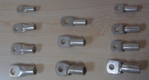
Figure 1: Cable lugs of different sizes
Usages
Cable lugs are used where there should be permanent connection and where applying direct connection is inconvenient. The methods of application may vary depending on the usage. Brazing or welding is performed based on the type of the lug to be connected. Then with a bolt, screw or clip, the connection end is connected by tightening it to the connection point with a terminal that is a full match. The metal that is the most often used for the lugs that are manufactured in many sizes and in different metal materials is copper. The lugs that are fork or ”U” shape are used for screw terminals; the lugs that are closed ring or “O” type are for bolt applications; and the with pins or flat handles are used for compressive or blade tipped terminals. The cable lugs are also used to reduce the cable size as they can connect a cable with a thicker cross-section to a smaller sized connector.

Figure 2: A type of lug that is used in cable cap application
Lug and Cable Compatibility
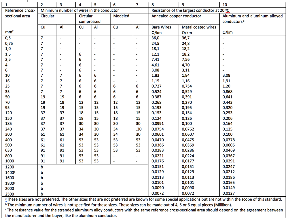
One of the first and most important stages of a cable design is the design of the conductor. The most common standard for the designing of the conductors is the IEC 60228. While designing and choosing the conductor, the geometric size and cross-sectioncut of the conductor are extremely important; but the most crucial parameter is the electrical cross-section, not the geometrical one. And this is achieved with the maximum correct current conductor resistant given for 1 km length at 20 ⁰C. The standards put forth the maximum conductor resistance condition for electrical cross-section, while they do not put forth any conditions for a geometrical cross-section, and just provide a geometrical diameter range for information and guide. The cable manufacturers in Turkey use the standard TS EN 60228:2007 as the “Turkish Standard” for conductors. For example; while the maximum conductor resistance and minimum wire number parameters of the Class 2 stranded conductors (in Table 1) are given as obligatory in TS EN 60228:2007, Chart 2 for the single and multicore cables, the conductor diameters for the relevant cross-sectionscuts are given in Chart C.2 in the “Additional Information” of the same standard (Table 2) for information purposes.
(For information)
Guide regarding the size limits of circular conductors
C.1 Purpose
This annex is intended as a guide to help the manufacturers of cables and cable connectors in making sure that the conductors and connectors are compatible in terms of their size. This annex provides a guidance for the size limits of the conductor types below within the scope of this standard.
a) Copper, aluminum and aluminum alloy circular solid conductors (Class 1),
b) Copper, aluminum and aluminum alloy circular compressed circular stranded conductors (Class 2)
c) Copper flexible conductors (Class 5 and Class 6).
C.2 Size limits for circular copper conductors
The diameters of the circular copper conductors must not exceed the values given in Chart C 1.
If the smallest diameters are needed for the Class 1 circular copper conductors, the smallest sizes can be referred to as shown in Chart C.3 for the solid circular aluminum or aluminum alloy conductors.
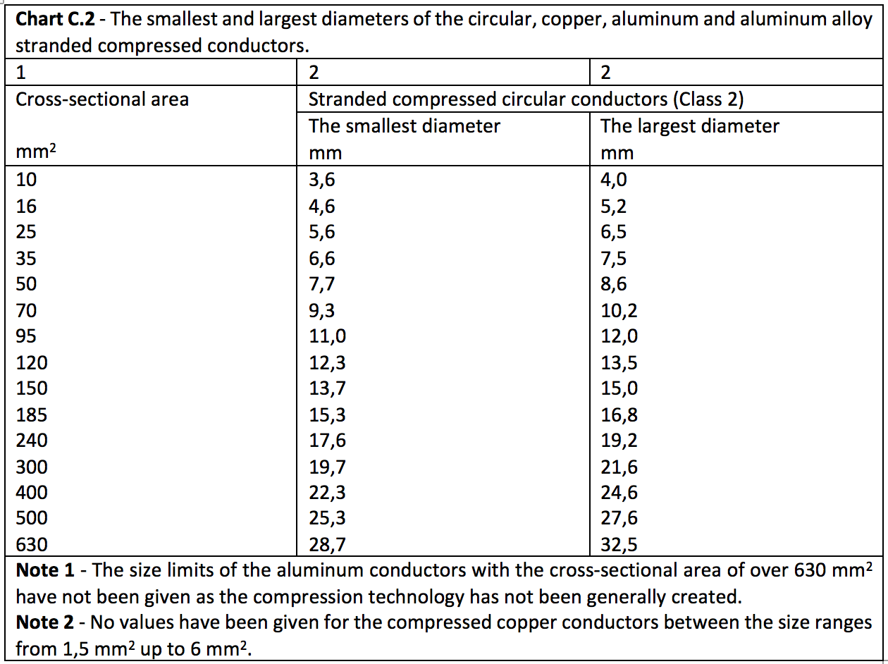
C.3 -Size limits for circular, copper, aluminum and aluminum alloy stranded compressed conductors
The diameters of the stranded compressed circular copper, aluminum or aluminum alloy conductors must not exceed the highest values and must not be less than the smallest values given in Chart C.2.
In the event that there are no compressed circular stranded aluminum or aluminum alloy conductors, the largest diameters must not exceed the values that are equivalent to the copper conductors given in column 3 in Chart C.1.
Table 2: TS IEC 60228: 2007, Chart C.2
This example applies to the other circular conductors as well. You can see the tables with the diameter information for the other conductor classes in the annex section of the standard TS EN 60228:2007.
The cable and conductor designs that we make as Prysmian Group Turkey are compatible with both the “maximum right current conductor resistance given for 1 km length at 20 ⁰C” as the standards have established, and with the “largest and smallest diameter” limits given as guidance. Thus, in order to shed light on the comments regarding the discordances from the market and to the questions asked to us, tests have been carried out three from each of the cable lugs designed for four different cross-sectionscuts (35,50,70 and 95 mm²) taken from three different lug manufacturers. It can be seen in the results of the test that we have carried out that our conductors are fully compatible with every lug sample that was correctly manufactured and with the right compression. This study has been shown comparatively in Table 3.
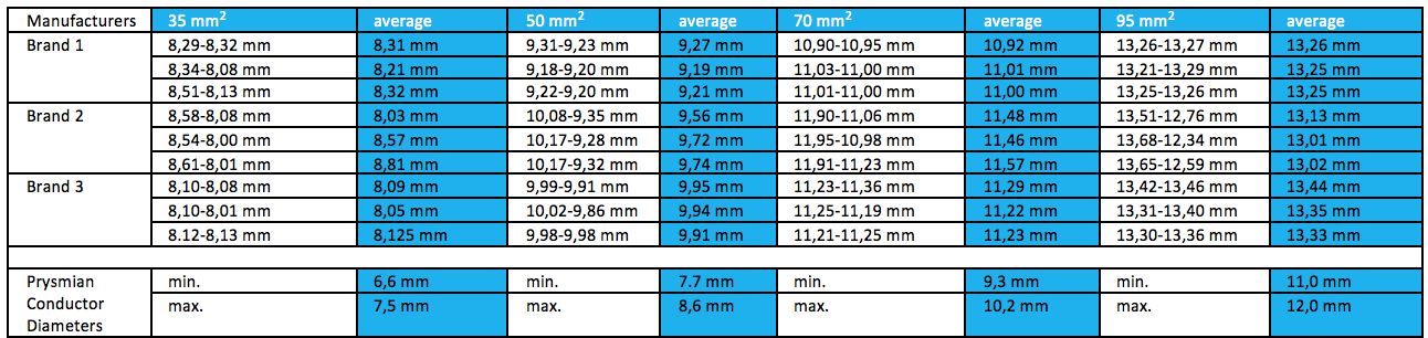
Table 3: The lug diameters of different lug manufacturers and the Prysmian Group conductor diameters
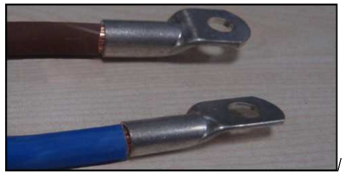
Figure 4: A type of lug that was directly connected to the cable end and that was correctly assembled.
Results That Might Occur Due to Improper Connection
Not only the requirement that the cable and lug materials to be connected must be compliant with the standards is open for discussion, but also correct connection and the type of connection are maybe the things that one must pay attention the most in terms of both long lifespan and for the safety of life and property. It is inevitable to encounter unwanted results due to faulty connection even if the right materials are chosen and used. And one of the most common mistakes is over-compression. The conductor at the connection point can be squished and damaged with over-compression. And since there can be torn wires with time due to reasons such as vibration, bending...etc., the electrical resistance of the conductor will get higher. And thus, there can be overheating. Overheating can result in fire in the event that the polymeric material used in the cable insulation exceeds its limit values and when that corrupts the chemical properties of the polymeric
material. And the way to prevent errors is to use a hydraulic compression device and to perform the calibration without delaying the period as recommended by the device manufacturer. Another error is not picking the right lug for the conductor cross-sectioncut of the cable to be connected. In the event that the lug that is picked is larger than necessary, there might not be a conjunction between the lug and the cable conductor’s contact surface at a desired level. And as a result, the arcs that might occur between the gaps at the connection point could once again damage the polymeric material and cause fire. And the way to prevent such situations is to pick the right materials compliant with the standards and make the right connection.
As Prysmian Group Turkey, we continue to share the studies that we carry out in order to raise awareness of the society and the users. Remember, the studies that we conduct and the systems that we install will shed light to the future generations to come.
Emre ŞİMŞEK
e-posta: [email protected]